ISO 5658, IMO FTPC PART 5 火焰擴散測試裝置 ISO 5658, IMO FTPC PART 5
ISO 5658, IMO FTPC PART 5
火焰擴散測試裝置 ISO 5658, IMO FTPC PART 5
Spread Of Flame Apparatus ISO 5658, IMO FTPC PART 5
廠牌:代理
供應商:大台北尖端儀器有限公司
聯絡電話:02-2531-0981
| 快速詢價 |
火焰擴散測試裝置
IMO FTPC第5部分,ISO 5658
火焰蔓延裝置測量船舶和鐵路應用中材料的火焰蔓延。
IMO船舶規範包括用於散熱測量的收集罩。
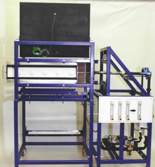
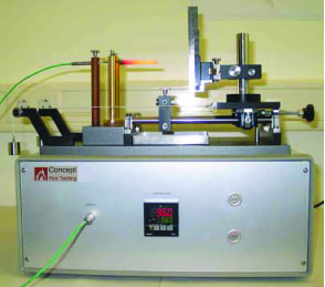
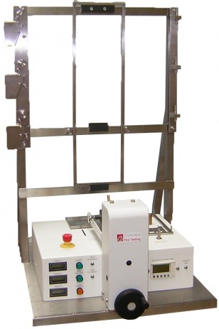
儀器是根據標準的要求構造的,主要包括兩個主要項目:輻射面板框架和品支持框架,以及許多補充項目。
規格和特點
輻射面板框架
輻射板的支撐框架由所有焊接的方管低碳鋼構件製成,並且包括輻射板的所有相關管道和控制閥。輻射面板的總尺寸約為480mmx 280mm,由安裝在不銹鋼外殼中的多孔耐火磚組成,安裝在旋轉鋼環上的支撐框架上,從而可以測試不同方向的樣品。
輻射面板設計用於天然氣或丙烷氣體,氣體在進入面板之前先與空氣混合。為氣體和空氣都提供了壓力調節器以及控制閥和截止閥。供氣管道中裝有可變面積流量計,以控制和監視向輻射板供應的氣體和空氣。
一個小的控制箱固定在框架上,其中包含與氣體安全系統相關的指示燈和按鈕。
樣品支持框架
支撐樣品的框架也由所有焊接方管低碳鋼製成。框架的一側包含用於承載樣品架的鋼製導軌。設備可用於將樣品沿水平面朝上放置。
當處於測試位置時,靠近輻射板一端的樣品表面靠近固定在支撐框架上的不銹鋼管發出的測試火焰,並從主要氣體供應源提供氣體/空氣混合物在輻射面板支持框架上。
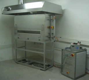
對於IMO規範,放熱煙囪安裝在樣品支撐框架上並直接位於樣品上方,以便從垂直安裝的煙囪中升起的燃燒產物被引導到煙囪中。
樣品支撐框架通過墊片和固定螺栓鏈接到輻射板的支撐框架。
樣品架
不銹鋼樣品架是根據規格要求製造的。還提供了一個彈簧加載快速夾具,可輕鬆加載和固定試樣。
校正系統
它由一個校正板和一個熱通量計組成。校正板由基於矽酸鈣的板材料製成,並設有一系列孔洞,當將校準板插入測試設備時,這些孔會將熱通量計放置在規定的校準位置。
熱通量儀是一種水冷箔熱通量儀,範圍為0 – 5 W /cm²,並帶有校正證書。儀表的輸出以mV為單位,並且可以在合適的記錄設備(未提供)或可選的數據採集和軟件系統上進行監視。
熱電偶調節裝置
它由一個專門製造的設備組成,該設備可以根據規範的要求調節放熱堆棧上熱電偶的輸出。
技術數據和要求
電氣:230 Volts AC 50 Hz 或 115 Volts AC 60 Hz
氣體:設備的輻射板可以燃燒丙烷或天然氣。 典型的氣體供應要求是在200 mm水位計的供應壓力下流量最高為0.8升/秒。
空氣:需提供最高10升/秒的空氣供應,並且供應壓力約為300 mm水位計
尺寸:輻射板的整體尺寸約為480 mm x 280 mm
Spread Of Flame Apparatus
IMO FTPC PART 5, ISO 5658
The Spread of Flame Apparatus measures the flame spread of materials in marine and railway applications.
The IMO marine specification includes a collection hood for heat release measurement.
The Apparatus is constructed in accordance with the requirements of the Standard and consists essentially of two main items, the Radiant Panel Framework and the Specimen Support Framework, and a number of supplementary items.
Specfication and Features
Radiant Panel Framework
The support framework for the radiant panel is manufactured from all welded square tubular mild steel members, and includes all the associated pipework and control valves for the radiant panel. The radiant panel, which has overall dimensions of approximately 480 mm by 280 mm and consists of porous refractory tiles mounted in a stainless steel housing, is mounted on the support framework on a rotating steel ring, allowing for the testing of specimens in different orientations.
The radiant panel is designed for use with natural gas or propane gas and the gas is mixed with air prior to entry to the panel. Pressure governors and control and shut off valves are provided for both the gas and the air. Variable area flowmeters are incorporated in the supply pipework to allow the gas and air supplies to the radiant panel to be controlled and monitored.
A small control box is fixed to the framework which contains indicator lamps and push buttons associated with the gas safety system.
Specimen Support Framework
The framework which supports the test specimen is also made from all welded square tubular mild steel sections. One side of the framework contains steel guides which carry the specimen holder. Facility is available for location of a test specimen in the horizontal face upwards orientation.
When in the test position, the surface of the specimen at the end adjacent to the radiant panel is brought close to a test flame issuing from a stainless steel tube fixed to the support frame and supplied with a gas/air mixture from the main gas supplies on the radiant panel support framework.
For the IMO Specification a heat release stack is mounted on the specimen support framework and directly above the test specimen, such that the combustion products rising from a vertically mounted specimen are channelled into the stack.
The specimen support framework is linked to the support frame for the radiant panel by spacers and fixing bolts.
Specimen Holder
The stainless steel specimen holders are manufactured in accordance with the requirements of the Specification. A spring loaded quick action clamp for easy loading and retention of the test specimen is also provided.
Calibration System
This consists of a calibration board and a heat flux meter. The calibration board is manufactured from a calcium silicate based board material and is provided with a series of holes which, when the calibration board is inserted into the test apparatus, positions the heat flux meter at prescribed calibration locations.
The heat flux meter is a water-cooled-foil heat-flux meter with a range of 0 – 5 W/cm², and comes with a calibration certificate. The output from the meter is in mV and can be monitored on a suitable recording device (not supplied) or from the optional Data acquisition and software system.
Thermocouple Conditioning Device
This consists of a specially manufactured device which enables the outputs from the thermocouples on the heat release stack to be conditioned as required by the Specification.
Technical Data & Requirements
Electrical: 230 Volts AC 50 Hz or 115 Volts AC 60 Hz
Gas : The radiant panel of the apparatus can burn propane or natural gas. Typical gas supply requirements are a flow of up to 0.8 litres/second at a supply pressure of 200 mm water gauge.
Air : An air supply of up to 10 litres/second and at a supply pressure of approximately 300 mm water gauge is required
Dimensions: The radiant panel has overall dimensions of approximately 480 mm by 280 mm




.jpg)
